
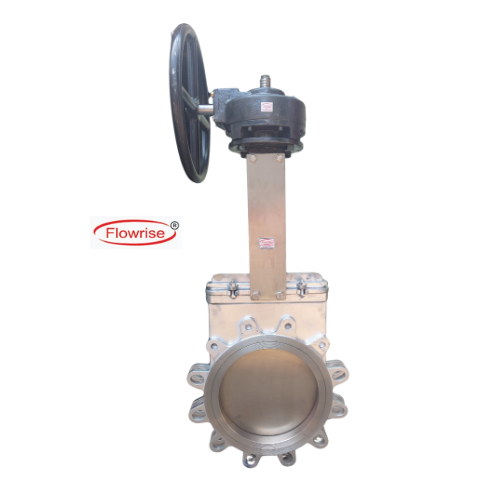
Gear Operated Knife Edge Gate Valve
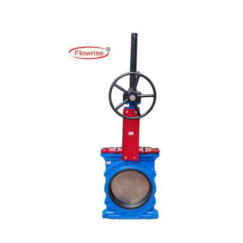
O Port Type Knife Edge Gate Valve
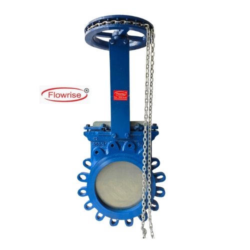
Chain Operated Knife Edge Gate Valve
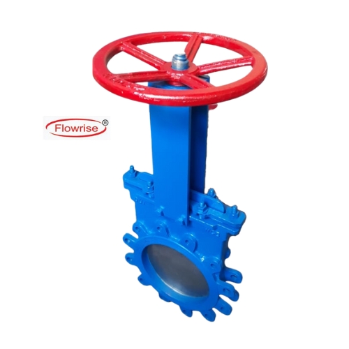
Manual Hand Wheel Operation Knife Edge Gate Valve
Cylinder - Pneumatic Operated Knife Edge Gate Valves Manufacturer In India
“FLOWRISE” Brand Knife Edge Gate Valves..
“FLOWRISE” brand Knife Edge Gate Valve is the specific design. This design ensures minimum contact between the parts of the valve, Reduces the wear & tear. The high performance Knife Edge Gate Valves feature. Non Sliding Motion, Avoid Sliding Contact between Body & Gate allow flushing of media form the valve interior. A wide variety of hardened trim options are available on Gate, Seat and Wear Ring. Batten edge of the gate (knife-edge) allows the tight shut off even when solid particles settles at the bottom of the Body.
Knife Edge Gate Valves Supplier
Knife-Edge Gate Valves in Mining, Power, Steel, Chemical, Paper and withstand high Temperature & Abrasive Slurries in Industries Ideal for high-density slurry lines.
Knife Gate Valves are Unidirectional Valves, Excellent Hopper Isolation Valves with their ability to cut through flowing media and closed by dislodging any material in the seating area. Knowing us as a reputed firm, Beena Engineering Works are engaged in manufacturing, supplying, as well as dealing a wide range of Knife Edge Gate Valves in Ahmedabad, Gujarat, India.
Type’s of Knife Edge Gate Valves in Gujarat
| Edge Gate Valves. | Uni-directional / Bi-directional Knife Edge Gate Valve |
| Body/Gate/Seat M.O.C. | Cast Steel / Cast Iron / S.G.Iron/SS 304 / 316 / 316L. |
| Body:Cast corrosion-resistant steel or cast iron to provide receptivity against corrosion For all whetted parts | |
| Stem:Stainless steel or as desire, having double start thread rising / non-rising spindle, For fast closing and opening. | |
| Gate:The Stainless steel knife gate plate is precision-buffed on both sides, to enhance Packing life and ensure positive shut off even heavy or high-viscous fluid. | |
| Seat:Renewable Metal-to-Metal, replaceable type, soft seat and other Suitable to application. | |
| Port Type : | Round Port, Lugged Type. |
| Valve End Connection : | Flange End / Uni Lugged, Wafer , Two Lug, Wafer Flange-less, |
| Sizes : | 50mm T0 800mm |
| Rating : | 10 bar up to 800mm for valves with body in C.S., S.S. and specially alloy, 10 bar Up to 300mm & 5 bar on higher sizes up to 800mm with body in Cast Iron / Ductile Iron. |
| Drilling : | Option Include ANSI, DIN, BS, JIS and AS standard; others on request |
| Operation Available : | Knife edge Gate Valves Operation – Manual, Cylinder Operated, Electrical Actuator, Pneumatic Actuator with Manual Override. |
| Widely Used For | “FLOWRISE” Brand Knife Edge Gate Valves for Slurry Lines, Sludge and Viscous Media Handling, Pulp and Paper Stock Lines, Dry Solid and Powder Handling, High Temperature Gas Lines and Many More. |
Knife Edge Gate Valve
Manual Override
Application
Selection of Body Material
- Cast Iron
- S.G.IRON
- Cast Carbon Steel
- SS 304 (CF8)
- S.S.316 (CF8M)
- S.S.316L (CF3M)
Seat Material
- SS 304
- SS 316
- SS 304L
- SS 316L
- Nitriding to approx 600-1250 HV1 surface hardness
- Replaceable EPDM Rubber, max. temp. up to 1200 cen.
- Replaceable VITON Rubber, max. temp. up to 2320 cen.
- Replaceable P.T.F.E., max. temp. 2100 cen.
Seat Material
- SS 304 / L
- SS 316
- SS 316L
Wheel And Ring Type, Knife Gate Valve
- Wheel type is ideal for Uniform operation.
- Gun Metal/Stainless Steel rings gives better life to the valve body and useful where more acidic materials are passing.
| 1 | Body-Cast Iron / Cast Steel / SS 304 / SS 316 |
| 2 | Frame- M.S |
| 3 | Gate – S.S .304 |
| 4 | Spindle – S.S. 304 |
| 5 | Wheel CI |
| 6 | Spindle Nut Gun Metal |
| Size | A | B | P.C.D | H | J | K |
| 40 | 315 | 35 | 98 | 125 | 355 | 1/2″ |
| 50 | 335 | 40 | 114 | 125 | 385 | 1/2″ |
| 75 | 385 | 45 | 146 | 175 | 460 | 1/2″ |
| 100 | 458 | 50 | 178 | 200 | 558 | 1/2″ |
| 125 | 508 | 55 | 210 | 200 | 633 | 1/2″ |
| 150 | 564 | 60 | 235 | 250 | 714 | 5/8″ |
| 200 | 706 | 65 | 292 | 300 | 906 | 5/8″ |
| 250 | 815 | 68 | 356 | 300 | 1065 | 5/8″ |
| 300 | 885 | 70 | 406 | 350 | 1185 | 3/4″ |
Gland Packing
Valve End Style
Design & Testing
Pneumatic Acutators
“FLOWRISE” Brand Cylinder Actuators provide a versatile method to automate Knife Edge Gate Valve. Air and Hydraulic cylinder actuators from Flow-age provide a versatile and cost effective method of automation. This adds up to a greater value for you. We offers different types of Cylinder Actuator suitable for Knife Gate & Slide Gate Valve. Cylinder Actuator is a double acting design and is available in a wide range of cylinder diameter and stroke lengths.
- Standard cycle duty Air cylinder up to 8 bar rated
- Specialized Heavy duty Hydraulic cylinder up to 210 bar rated
- Specially design for high cycle duty Air cylinder up to 15 psi rated
Type: Double Acting
- Cylinder Size Range: 2.5” to 16” and other respected to service condition
- Rating: Suitable for normal operation with Air supply up to 8 bar. Cylinder tube tasted at 20 bar.
- Cylinder Tube – Aluminium Grey Color Double Powder Coated
- Piston – Cast Iron
- Piston Seals- Neoprene Rubber
- Piston Rod – Steel with Hard Chrome Plated (Others available on request)
- Piston Rod Seal – Neoprene Rubber
- Top & Bottom end Cap – Cast Iron with Black Color Double Powder Coated
- Tie Rods – Steel
- Air Connection – ¼” To 1” NPT (F)
Limit Switches
- Design – Mechanical, Proximity Switch
- Type – SPDT: (01 N/O + 01 N/C)
- DPDT: (02 N/O + 02 N/C)
- Enclosure – Weather Proof, IIA, IIB, IIC
Air Filter Regulator
- ¼” To ¾” NPT (F)
Soenoid Valve
- Type – 5 x 2 Way
- Body – Aluminum, Brass, S.S.
- Coil Voltage – 220 V. / 110 V. / 24 V. D.C.
- Weather Proof, Ex-Proof, IIA, IIB, IIC
- Size – ¼” To 1”
I/P Converter
- Design – Mechanical, Proximity Switch
- Type – SPDT: (01 N/O + 01 N/C)
- DPDT: (02 N/O + 02 N/C)
- Enclosure – Weather Proof, IIA, IIB, IIC
Speed Control Valve
- Needle valve to control the speed of actuator operation during open & close
- Body – S.S., Aluminum, Brass
- Size – ¼” to ½” NPT (F)
Pneumatic Tubing & Fittings
- Tubing M.O.C.: Copper, PVC Covered Copper, Stainless Steel
- Fittings M.O.C.: Brass, Stainless Steel
- Size: ¼” To ½”
| Body | MSS SP-81 requires the valve body (pressure vessel and related structure) to designed for and hydrostatically pressure tested to 1.5 times the rated working pressure |
| Valve rated pressure – 150 psi | |
| Body test pressure – 225 psi | |
| Gate | MSS SP-81 requires the gate to be designed for and hydrostatically pressure tested to 1.1 times the rated working pressure |
| Valve rated pressure – 225 psi | |
| Gate test pressure – 165 psi | |
| Seat | MSS SP 81 has an allowable leakage rate (for metal to metal seated valves) of 40 cc per inch of diameter, per minute at 40 psi pressure. On a 12” valves this would be equal 40 times 12, or 480 cc per minute at 40 psi. |
| Maximum allowable leakage of 0.6 GPM when tested with water at 40 psi applied in the normal flow direction. | |
| No visible leakage when tested with water at 40 psi (For Soft seated valves only) | |
| Face To Face | MSS-SP-81 has specified face-to-face dimension and tolerance of each valve size to assure ease of installation for the consumer, regardless of the valve manufacturer. See catalogue for dimension. |
| No. | Body Parts Name | M.O.C. of Parts |
| 1 | Body | C.I./WCB/CF8/CF8M / Duplex |
| 2 | Yoke | C.I./WCB/CF8/CF8M |
| 3 | Yoke Bush / Sleev | C.S. |
| 4 | Disc | S.S. 304 / 316 |
| 5 | Gland | C.I./WCB/CF8/CF8M |
| 6 | Gland Stud & Nut | C.S. |
| 7 | Gland Packing | Graphite / PTFE |
| 8 | Seat | Soft / Metal |
| 9 | Seat Ring | CF8 / CF8M |
| 10 | Seam / Spindle | S.S. 304 / 316 |
| 11 | Spindle Pin / Stud & Nut | S.S. 304 / 316 |
| 12 | Nut | C.S. |
| 13 | Wheel | C.I. |
| 14 | Design | Lug / Wafer |
| Size | A | B | C | D | E |
| 50 | 48 | 203 | 310 | 335 | 468 |
| 80 | 51 | 203 | 375 | 425 | 560 |
| 100 | 51 | 203 | 420 | 495 | 622 |
| 125 | 57 | 254 | 470 | 565 | 726 |
| 150 | 57 | 254 | 510 | 625 | 789 |
| 200 | 70 | 305 | 610 | 775 | 958 |
| 250 | 70 | 406 | 665 | 915 | 1109 |
| 300 | 76 | 406 | 755 | 1055 | 1280 |
| 350 | 76 | 508 | 885 | 1240 | 1436 |
| 400 | 89 | 508 | 900 | 1300 | 1495 |
| 450 | 89 | 508 | 1025 | 1485 | 1676 |
| 500 | 114 | 508 | 1140 | 1640 | 1891 |
| 600 | 114 | 508 | 1340 | 1960 | 2195 |
Technical Specification
| Design Std. | MSS-SP81 |
| End Eonnection | Lugged To Asme (Ansi)B 16.5 RF 150# Flanged / Wafer |
| Face to Face | MSS-SP81 |
| Testing Std. | MSS- SP81 |